2022年11月14日星期一

GLSUN Optical Switch


Fiber optic network switch, or fiber switch, is a multi-port telecommunication network bridge device to connect multiple optic fibers to each other and controls data packets routing between inputs and outputs. More exactly, a fiber optic network switch receives a message from any device connected to it and then transmits the message only to the device for which the message was meant. This makes the fiber optic switch a more intelligent device than a hub (which receives a message and then transmits it to all the other devices on its network). The fiber Ethernet switch plays an integral part in most modern Ethernet local area networks (LANs). Mid-to-large sized LANs contain a number of linked managed switches. #fiberopticswitch #fiberswitch #all-opticalswitch #opticalswitch


https://www.glsunmall.com/product/fsw-d2x2b-optical-switch.html

2022年11月10日星期四

GLSUN MEMS optical switch


MEMS optical switch
 is based on micro-electro-mechanical system, which uses optical micro mirrors or optical micro-mirror arrays to change the propagation direction of light beam to achieve optical path switching. The working principle of MEMS optical switch is quite simple. When the optical switching is carried out, the angle of MEMS micro mirror is moved or changed by electrostatic force or magnetic force, and the input light is switched to different output ends of the optical switch to realize the switching and on-off of the optical path.#MEMS #MEMSOPTICALSWITCH #OPTICALSWITCH  


https://www.glsunmall.com/product/mems-ms-1x8-optical-switch.html

EDFA Working Principle


The erbium-doped fiber (EDF) is at the core of EDFA technology, The erbium-doped fiber in the erbium-doped fiber amplifier is doped with erbium element, and the erbium-ion energy is high and very unstable, and it is easy to jump to the low energy level through various ways. Under the energy transmission of the pump source, a large number of erbium-ion stacks and then realize the inversion of the particle number, creating conditions for stimulated radiation.#edfa #wdm #optical #amplifier #fiberamplifier #amplifier

https://www.glsunmall.com/products/optical-amplifier.html


2022年11月5日星期六

Optical Transmission System

GLSUN optical transmission system is mainly composed of transmitter, transmission medium, and receiver. It offers kinds of highly efficient transmission by using optical transmission technologies in accordance with different applications for networking solutions


2022年10月13日星期四

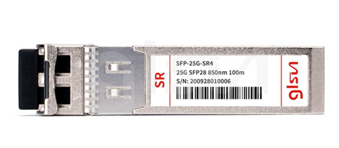
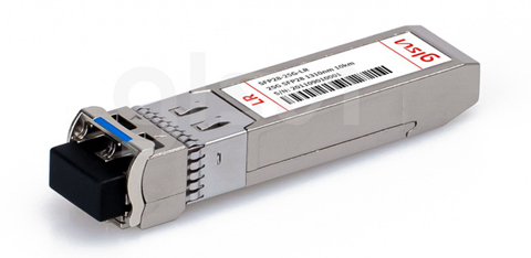
What is 25G SFP28 Optical Transceiver Module

 The data rate of optical modules has upgraded from 100 Mbps to 1 Gbps to 10G, 25G, 100G and even 400G for development of fiber optic communication. Among them, SFP28 transceiver module is an optical module with a transmission rate of 25Gbps. SFP28 stands for small form-factor pluggable 28. It features low power consumption, high port density and can save the cost of network deployment, so it is widely used in 25G Ethernet and 100G (4X25Gbps) Ethernet.

Advantages of 25G SFP28 Transceiver Modules

1. Compared with 100G optical modules, SFP28 modules have lower loss.

2. Compared with 40G optical modules, SFP28 modules are more cost-effective. SFP28 modules can adopt two fiber channels to achieve 50G transmission rate, while 40G modules need four 10G fiber channels to achieve 40G transmission rate

3. Compared with 10G optical modules, SFP28 modules have 2.5 times the optical input/output performance that of 10G modules, and feature higher port density, thus can save operating costs by reducing the number of ToR switches and cable.

Categories of 25G SFP28 Modules

There are mainly 2 types, SFP28-25G-SR, and SFP28-25G-LR.

SFP28-25G-SR

They are compliant with IEEE 802.3, SFF-8472, SFF-8402, SFF-8432, SFF-8431 and other standards. It is an SFP28 optical module with center wavelength of 850nm, supporting DOM (Digital Optical Monitoring) function to help manage the real-time monitoring of optical modules. Its difference from other SFP28 optical modules lies in its transmitter type - VCSEL (vertical-cavity surface-emitting laser), so it requires the use of 50/125µm MMF OM3/OM4 patch cables. The SFP28-25G-SR modules are sui for short-distance data transmission (max. 100m) and can be used in 25G Ethernet switches, routers, network interface cards (NIC) and storage network devices.

SFP28-25G-LR

They are also compliant with IEEE 802.3, SFF-8472, SFF-8402, SFF-8432, SFF-8431 and other standards. It is an SFP28 optical module with center wavelength of 1310nm, and its maximum transmission distance can reach up to 10km being used together with single mode fiber, therefore SFP-25G-LR modules are mainly used in long distance transmission (max. 10km). Its difference from SFP-25G-SR modules lies in that it uses DFB laser transmitter.

2022年9月22日星期四

Advantages and Technologies of All Optical Network

In the existing communication networks based on optical multiplexing, the completion of optical/electrical/optical conversion of each node in the network is still exchanged at the speed of electrical signals processing information. In order to meet the requirements of high speed and large capacity, the electronic components have some disadvantages such as bandwidth limitation, clock offset, serious crosstalk and high power consumption, which brought forth "electronic bottleneck" in communication network. In order to solve this problem, the concept of all-optical network (AON) was put forward. With its good transparency, wavelength routing characteristics, compatibility and scalability, all-optical network has become the first choice of the next generation of high-speed broadband networks.

What is All Optical Network

The all-optical network refers to the whole process of data transmission and exchange from the source node to the end user node are all conducted in the optical domain, that is, end-to-end complete optical path, without the intervention of electrical signals. `

Advantages of All Optical Network

The all-optical communication network based on WDM can enable the communication network to have stronger manageability, flexibility and transparency.  It has the following advantages over the previous communication network and the current optical communication system. 

1. It reduces the use of electronic devices. The flow of optical signal in all-optical network no longer meets the obstacle of photoelectric conversion, which overcomes the difficulty of improving the signal rate of electronic devices on the way, saves a large number of electronic devices, and greatly improves the transmission rate.  

2. It supports multiple protocols. All optical network adopts wavelength division multiplexing technology and selects routing by wavelength, which can provide services of multiple protocols conveniently.

3. It provides high networking flexibility. The all-optical network is very flexible, and a certain wavelength can be extracted or added at any nod

4. It is of high reliability. There is no transformation and storage along the way, and many optical devices in the all-optical network are passive, so it is highly reliable.

Key Technologies in All Optical Network

1. Optical Switching Technology

Optical switching technology can be divided into optical path switching technology and packet switching technology. Optical path switching can be divided into three types, namely, space division (SD), time division (TD) and wave division/frequency division (WD/FD) optical switching, and the combination of these switching forms. In optical packet switching, asynchronous transmission mode is a widely studied mode in recent years.

2. Optical Cross Connection Technology

OXC is a device used in fiber optic network nodes. By cross-connecting optical signals, OXC can flexibly and effectively manage fiber optic transmission networks. It is an important means to achieve reliable network protection/recovery and automatic wiring and monitoring. OXC is mainly composed of optical cross connection matrix, input interface, output interface, management control unit and other modules. To improve OXC reliability, each module has active and standby redundancy structures, and OXC automatically performs active/standby switchover.

3. Optical Add and Drop Multiplexing Technology

In the field of WDM optical networks, more attention is being focused on optical add and drop multiplexers. These devices have the functions of traditional SDH add-and-drop multiplexers (SDHADM) in the time domain in the optical wavelength domain. OADM, in particular, can split a channel from a WDM beam (split function) and generally new information into the optical carrier at the same wavelength ( function). For OADM, there must be a high degree of isolation between the sub-outlet and the insertion port, as well as between the input port and the output port, to minimize the same wavelength interference effect, otherwise the transmission performance will be seriously affected.

4. Fiber Amplifier Technology

Optical amplifier is one of the core technologies for building all-optical communication networks, and also the key element of dense wavelength Division multiplexing (DWDM) systems. The traditional basis of DWDM systems is erbium-doped fiber amplifier (EDFA). The optical fiber has a wide and low loss bandwidth in the 1550 nm window, which can accommodate the optical signals of DWDM to be transmitted on one optical fiber at the same time. After the appearance of EDFA, it quickly replaced the electrical signal regeneration amplifier and greatly simplified the whole optical transmission network.


2022年9月16日星期五

MUX and DEMUX in WDM

 WDM (Wavelength Division Multiplexing) is to combine a series of optical carrier signals at different wavelengths carrying various information at the transmitter through the Multiplexer and couple them to the same optical fiber for transmission.  At the receiver end, the optical signals are separated from each other by a Demultiplexer. The simultaneous transmission of two or many optical signals of different wavelengths in the same fiber is called Wavelength Division Multiplexing (WDM). WDM technology can double the transmission capacity of a single light, which can easily expand the capacity of existing optical networks. Depending on the direction of the transmitted signal, WDM can be used for multiplexing or demultiplexing.


MUX


The main function of MUX is to combine multiple signal wavelengths into one optical fiber for transmission. At the transmitter end, N optical transmitters operate at N different wavelengths, which are separated by appropriate intervals. These N light waves are respectively modulated by the signal as carriers and carry the signal. A wave synthesizer combines these different wavelengths of optical carrier signals and couples them into a single-mode fiber. Because the optical carrier signals of different wavelengths can be regarded as independent of each other (without considering the non-linearity of the fiber), the multiplexing transmission of multiple optical signals can be realized in one fiber. Through multiplexing, communication operators can avoid maintaining multiple lines and effectively save operating costs.


DEMUX


The main function of DEMUX is to separate multiple wavelength signals transmitted in one fiber. At the receiving end, the optical carrier signals of different wavelengths are separated by a demultiplexer, which is further processed by the optical receiver to recover the original signal. A demultiplexer (Demux) is a device that performs reverse processing on a multiplexer.  


Performance Parameters of MUX/DEMUX


1. Operating Wavelength


Multiplexer/demultiplexer operating waveband. For example, 1550 wavelength has three bands: S band (short wavelength band 1460~1528nm), C band (conventional band 1530~1565nm), L band (long wavelength band 1565~1625nm).


2. Number of channels & channel spacing


Channel number refers to the number of channels that a multiplexer/demultiplexer can combine or separate. This number can range from 4 to 160 to enhance the design by adding more channels. Common channels are 4, 8, 16, 32, 40, 48, etc. Channel spacing is the difference between the nominal carrier frequencies of two adjacent channels and is used to prevent inter-channel interference. According to ITU-T G.692, the channel intervals less than 200GHz(1.6nm) include 100GHz (0.8nm), 50GHz (0.4nm) and 25GHz. Currently, 100GHz and 50GHz channel intervals are preferred.


3. Insertion Loss


Insertion loss is the attenuation caused by the insertion of WDM in optical transmission system. The attenuation effect of WDM on optical signal directly affects the transmission distance of the system. Generally, the lower the insertion loss, the less signal attenuation.


4. Isolation


Isolation refers to the isolation degree between signals of each channel. High isolation values can effectively prevent the distortion of transmitted signals caused by crosstalk between signals.


5. PDL (Polarization Dependent Loss)


PDL refers to the distance between the maximum and minimum loss caused by different polarization states at fixed temperature, wavelength and the same band, namely, the maximum deviation of insertion Loss in all input polarization states.